
Use it with your own records.
- Download the workbook and open 31 Valve tags.
- Enter your site and room scope and the project or policy reference.
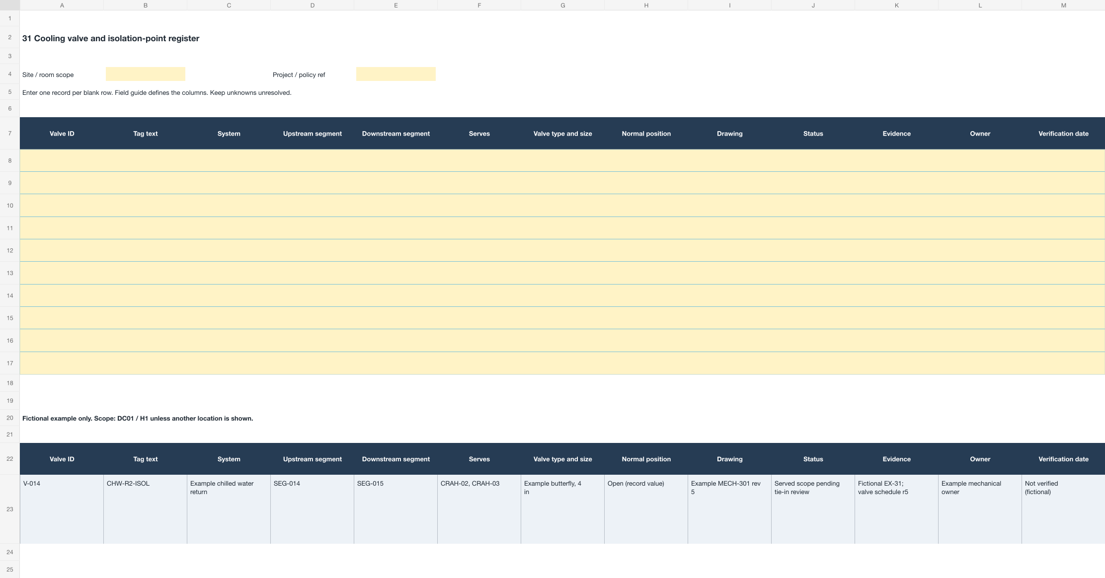
- Use the blank amber table for actual records. The fictional example below it is a reference.
- Insert table rows when needed. Keep identifiers as text, including leading zeros.
- Follow guide 31 to complete the checks and record unresolved items.
Before you start
- Define the included valves and the full location scope, separating individual valve bodies from the isolation positions they occupy.
- Collect the controlling mechanical drawing and its revision, the existing valve schedule, and any tie-in or change package affecting the boundaries in scope.
- Confirm how local policy distinguishes valve identity, tag text, segment references, and the served scope beyond the valve.
- Prepare an accepted observation method and record any access or readability limitation before treating a row as complete.
Complete the register
- Enter the Valve ID as the individual object or approved isolation position, retaining competing observed identities in the finding history.
- Transcribe Tag text exactly as observed, preserving partial or damaged content rather than reconstructing the intended number.
- Record the upstream and downstream segment references from the controlling drawing, not from the apparent direction of the pipe run.
- Enter Serves as the equipment or spaces fed by the isolated portion, listing identities instead of an area description.
- Record Normal position only as a documented value, and keep any observed position as a separate dated finding.
- Link the change reference, owner decision, and boundary history, showing the former claim, the current claim, and the event between them.
- Attach evidence for each row and state whether the valve position was observed or taken from the drawing.
Walk through the example
For the fictional VCASE-G31-301 survey in DC01 / H1, record the observed tag text CHW-R2-ISOL, the schedule claim naming SEG-G31-015, and drawing MECH-G31-301 revision 5 as three separate values before deciding anything. Cite tie-in package TIE-G31-301 as the event that may have moved the boundary. DEC-G31-014 establishes that VLV-G31-014 still bounds SEG-G31-015 but that the downstream portion now serves CRAH-G31-302 and CRAH-G31-303. Update the served-scope field, leave the tag text unchanged because it remains correct, and retain the former served scope with its effective revision. Link EV-G31-307 and review the other valves named in the tie-in, recording the two found correct as reviewed. Record the actual review date with any access limitation. The completed row explains which isolation claim was reconciled to which revision; it does not assert that closing the valve isolates either unit in practice.
Handle common exceptions
A valve is present in the field but absent from the schedule.
Record it as observed with no schedule entry and refer it to the mechanical owner. Do not assign the next unused number, which may belong to a change package or indicate the wrong drawing revision.
Two tags in the same system carry the same number.
Preserve both observed faces with their exact locations and refer the duplicate. Do not decide in the worksheet which one is original.
The valve is above a ceiling or behind a panel and cannot be observed.
Record the position as drawing-derived, name the access limitation as the evidence gap, and keep the row unconfirmed until the accepted observation method supports it.
Review and close
- Confirm every row carries a drawing revision and that the revision matches the one governing the tie-in history.
- Check that served scope names equipment or spaces rather than a room-level or row-level description.
- Keep superseded isolation claims retrievable with their effective references rather than overwriting them.
- Review the other valves named in the same change package for the same stale-scope pattern, and record those reviewed as unchanged.
- Record the actual verification date and retain access limitations separately from any mechanical or commissioning acceptance.
Fields and filled example
Fictional values only. Scope: DC01 / H1 unless another location is shown. The downloadable register is blank for your actual observations.
| Field | What to record | Fictional example |
|---|---|---|
| Valve ID | Local identity of the individual valve or isolation position. | V-014 |
| Tag text | Tag content preserved exactly as observed. | CHW-R2-ISOL |
| System | Fluid system and service role from the pipe identification. | Example chilled water return |
| Upstream segment | Segment reference on the supply side of the valve. | SEG-014 |
| Downstream segment | Segment reference isolated when the valve closes. | SEG-015 |
| Serves | Equipment or spaces fed by the isolated portion. | CRAH-02, CRAH-03 |
| Valve type and size | Documented type and size for the installed valve. | Example butterfly, 4 in |
| Normal position | Documented normal position, marked as a record value. | Open (record value) |
| Drawing | Controlling mechanical drawing and revision. | Example MECH-301 rev 5 |
| Status | Identity-review state or unresolved detail. | Served scope pending tie-in review |
| Evidence | Observation and record references supporting the row. | Fictional EX-31; valve schedule r5 |
| Owner | Team responsible for the mechanical system. | Example mechanical owner |
| Verification date | Actual date the isolation claim is reviewed. | Not verified (fictional) |
Sources and scope
- ASME: A13.1 piping identification ↗
Public scope overview only; no complete color or placement specification was accessed.
Read scope and linked guides - OSHA: 29 CFR 1910.145 ↗
US accident-prevention signs and tags; operational identifiers have a different function.
Read scope and linked guides