
Use it with the field guides
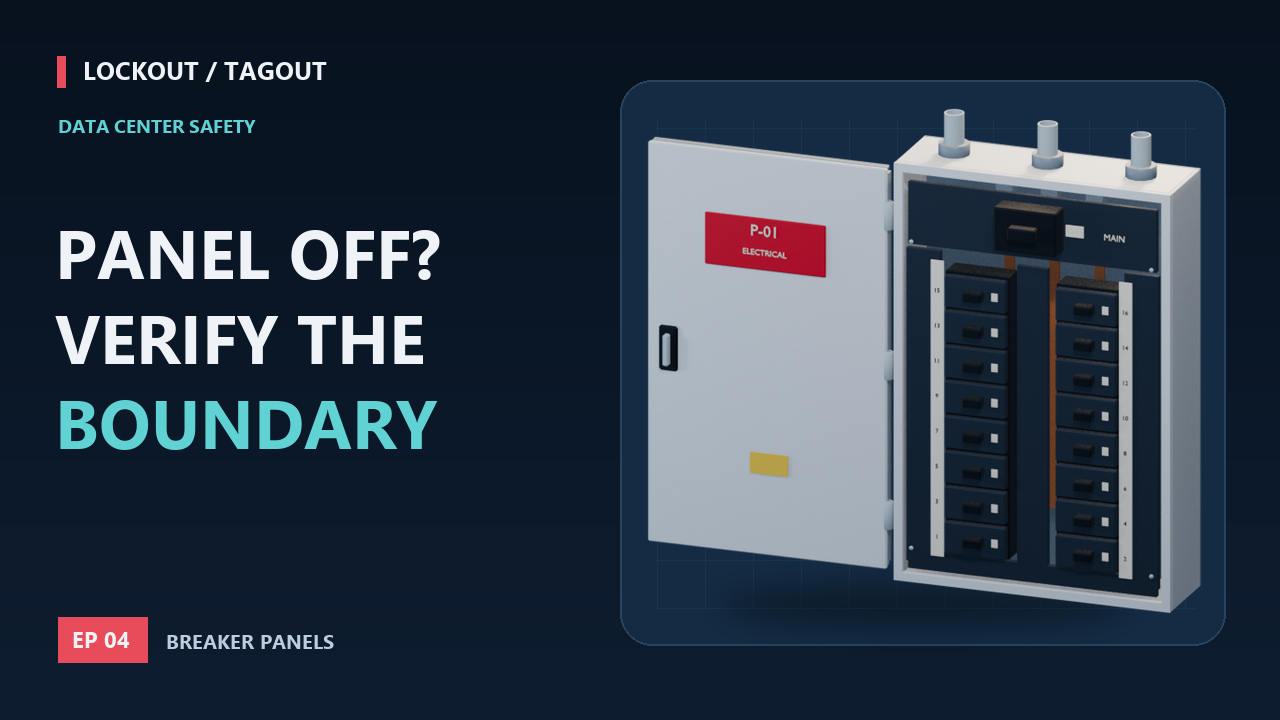
Match the equipment, circuit, disconnect, and actual work boundary before drawing conclusions from a panel label. The example explains why opening a branch breaker does not make the entire enclosure safe.
- The supplying circuit or disconnect is unclear
- A and B feeds are easy to confuse
- Nobody can tell which tap-off box feeds which rack
Educational examples for safety professionals. Actual work requires trained personnel, the employer’s equipment-specific energy-control procedures, and the manufacturer’s instructions. Watching does not confer authorization or electrical qualification.
Chapters
Jump to a transcript section; its time link opens that moment on YouTube.
- 0:00 Which equipment are we protecting?
- 0:46 Plan the data center switching conditions
- 1:29 Trace normal, alternate, and stored sources
- 2:12 A branch lockout has a limited scope
- 2:55 Opening the main has a limit too
- 3:40 Secure the specified disconnecting means
- 4:27 Verification is a qualified electrical task
- 5:11 Prove the tester, then interpret the result
- 5:55 Maintain the boundary through restoration
Full transcript
Read or save the Markdown transcript. Published October 2, 2026. Original 3D animation, AI-assisted scripting, and synthetic English narration.
Which equipment are we protecting?
0:00 on YouTube ↗The phrase lock out the panel hides an important question: what work is actually being done? Is the team servicing a downstream fan? Working on a branch circuit? Or opening the panel to work on its internal components? Those tasks can require different isolation boundaries. In this episode, the transparent views are conceptual illustrations, not instructions to remove covers. Real electrical isolation and testing require qualified personnel and the applicable electrical safety program. The first decision is the point of work. Only then can the team identify every circuit and source that could energize the parts people will be exposed to.
Plan the data center switching conditions
0:46 on YouTube ↗A data center adds operational complexity because distribution paths are designed to maintain service. Before switching, operations and the work team review the current one-line, equipment identification, load conditions, and the proposed maintenance boundary. If a load will be transferred, confirm that the remaining path can support the intended condition and that the switching plan is approved. These are planning activities, not proof of personnel protection. An approved change ticket does not replace lockout or electrical verification. Keep the operating objective and the worker-protection objective explicit so that neither is mistaken for completion of the other.
Trace normal, alternate, and stored sources
1:29 on YouTube ↗Trace sources all the way to the point of work. Depending on the installation, that may include normal supply, another feeder, a UPS output, a bypass path, a generator-supported bus, or a source connected elsewhere in the system. Also account for stored energy within the equipment. The animated line drawing is deliberately simplified. It is a prompt to ask whether a path exists, not a claim that every data center has the same wiring. Cross-check labels against the installed system. If the drawing shows one supply but the equipment or field wiring suggests another, resolve the conflict before the isolation plan proceeds.
A branch lockout has a limited scope
2:12 on YouTube ↗Watch this conceptual branch circuit. Opening its breaker interrupts the intended path to one downstream load. The supply bus on the other side of that breaker can still be energized. Other branches can remain energized too. The lockout device holds the selected operating mechanism in its isolation position; it does not change the state of every conductor behind the cover. If the job is inside the panel, the team must identify and isolate the sources relevant to that exposure, including the incoming side where necessary. Never let the presence of a padlock create a larger mental safety boundary than the actual isolation provides.
Opening the main has a limit too
2:55 on YouTube ↗Opening a main device is also not a universal answer. In a typical arrangement, the device can interrupt its downstream path while incoming terminals remain connected to their source. Other arrangements can have additional supplies or backfeed conditions. Our cutaway keeps the incoming side highlighted to make that distinction visible. The required upstream isolation depends on the actual system and the parts that will be exposed during the task. A panel-door lock only controls access to the enclosure; it is not a substitute for securing the relevant energy-isolating devices. The correct boundary is established by the procedure and verified at the work location.
Secure the specified disconnecting means
3:40 on YouTube ↗After the required planning and orderly shutdown, the specified disconnecting means are operated and secured under the electrical lockout procedure. In a compatible installation, the clamp secures the operator and a padlock retains its release mechanism. Real breaker accessories differ: a pin-style device, a clamp, or an integral lockable handle cannot be interchanged just because they look similar. The lock and tag arrangement must meet the applicable requirements, with the employee's identity and prohibition on unauthorized operation clear. A control switch, an emergency stop, or an interlock does not replace disconnection from the relevant electrical sources. Fit, point identification, and complete source coverage all matter.
Verification is a qualified electrical task
4:27 on YouTube ↗Before the exposed parts are considered deenergized for work, a qualified person verifies the condition. That includes the relevant restart check and electrical testing of the parts to which people will be exposed, including possible induced voltage or backfeed. The task must use appropriate test equipment, protective measures, and protective equipment for the exposure until the safe condition has been established. A stopped fan, a dark pilot light, or a screen message cannot replace this test. Nor is a casual scan with a noncontact indicator sufficient proof of every conductor's condition. The planned test must actually cover the work boundary.
Prove the tester, then interpret the result
5:11 on YouTube ↗The live-dead-live concept addresses a deceptively simple problem: a failed instrument can appear to show no voltage. A suitable known source is used to confirm the tester's operation before and after the absence-of-voltage test, following the electrical safety program and the tester's instructions. The actual circuit tests must cover the required conductors and combinations for the system. This graphic explains the logic, not probe placement for an unidentified panel. If the instrument does not respond correctly, or any result is unexpected, the condition is not established. Stop, resolve the cause through the proper procedure, and repeat the required verification.
Maintain the boundary through restoration
5:55 on YouTube ↗Verification establishes the condition for the defined work, not for every future change. If the task expands, another supply is introduced, or the isolation is disturbed, the plan must be reassessed. When work is complete, perform the applicable inspections, clear tools and temporary measures as required, position people safely, and complete notifications and lock removal through the approved process. Then restore the intended operating configuration. For the safety professional reviewing the job, ask the worker to point to the exact protected boundary. If the answer is simply that the panel has a lock on it, ask for the source map and verification evidence behind that answer.
Episode reference links
These are the primary references used in the episode. Manufacturer documents apply to the equipment they describe; the animation is conceptual. Check the actual installation, applicable requirements, and current equipment instructions before planning work.
- OSHA 29 CFR 1910.333 - Selection and use of work practices ↗
- OSHA eTool - Required content of energy-control procedures ↗
- OSHA eTool - Multiple energy sources ↗
- Schneider Electric - How does a UPS system work? ↗
- Master Lock 506 - Clamp-style breaker lockout mechanism ↗
- Fluke - About absence of voltage testing ↗
- Fluke - How to verify electrical test-tool operation ↗
- OSHA eTool - Release from lockout/tagout ↗