
Use it with the field guides
Bring the series together with a fictional fan inspection. Follow the planning and control sequence, and see where equipment identity, isolation-point records, verification, and communication each belong.
- Facility equipment names do not match alarm names
- Asset stickers and safety labels get mixed up
- Identify cooling valves and isolation points
Educational examples for safety professionals. Actual work requires trained personnel, the employer’s equipment-specific energy-control procedures, and the manufacturer’s instructions. Watching does not confer authorization or electrical qualification.
Chapters
Jump to a transcript section; its time link opens that moment on YouTube.
- 0:00 The job: inspect cooling fan F-01
- 0:43 1. Prepare and identify
- 1:32 2. Coordinate and notify
- 2:16 3. Shut down in an orderly way
- 2:56 4. Physically isolate the sources
- 3:40 5. Secure the isolation
- 4:22 6. Control stored and residual energy
- 5:06 7. Verify before exposure
- 5:49 8. Join the protected work and maintain control
- 6:32 If testing needs temporary energization
- 7:17 9. Inspect, clear, and release
- 8:01 10. Notify and restore deliberately
Full transcript
Read or save the Markdown transcript. Published October 2, 2026. Original 3D animation, AI-assisted scripting, and synthetic English narration.
The job: inspect cooling fan F-01
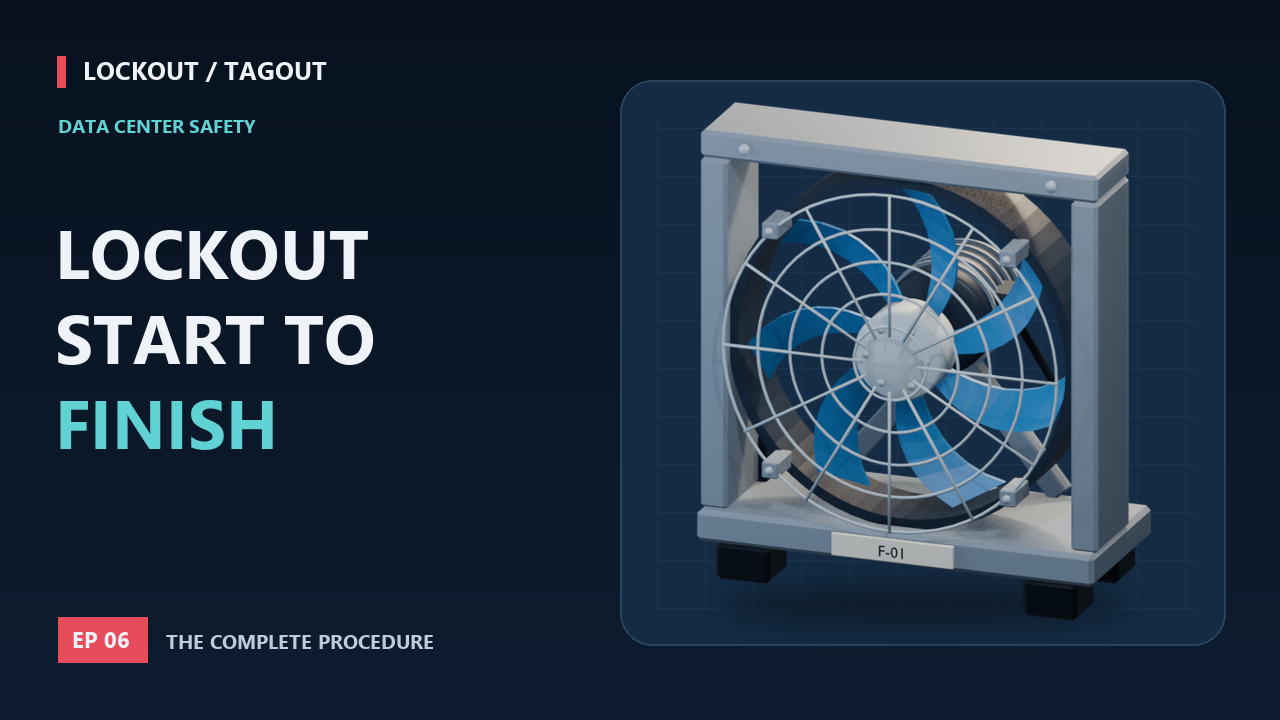
0:00 on YouTube ↗Our final scenario is an internal inspection of cooling fan F-01 in a fictional data center. The names and energy paths are illustrative. They are not a switching schedule for real equipment. We will follow the complete logic from planning to return to service, using an employer's written equipment-specific procedure. The fan and drive create electrical and mechanical concerns. Any other sources are included when they can create exposure for this task. The scene does not require opening the cooling-water circuit, so it does not casually shut valves elsewhere in the facility. The boundary follows the actual work and its hazards.
1. Prepare and identify
0:43 on YouTube ↗First, prepare. The authorized employees review the task, equipment identifier, procedure, energy types and magnitudes, isolation points, stored-energy controls, and verification methods. Electrical tasks are assigned to appropriately qualified personnel. The team confirms that the drawing, labels, and physical installation describe the same equipment. Operations reviews the planned cooling and electrical conditions so the shutdown can occur safely. Tools, compatible lockout devices, and required protective measures are ready before switching begins. The first hold point is identification: if any source, label, or procedure does not match the field condition, stop and resolve the discrepancy.
2. Coordinate and notify
1:32 on YouTube ↗Next, coordinate the people. The employer or authorized employee notifies affected employees before the energy controls are applied. The pre-job discussion identifies who is doing the work, who is coordinating it, and what equipment will be unavailable. Any outside employer exchanges the relevant lockout procedures with the on-site employer. In this example, three authorized employees will participate using the approved group arrangement. Everyone understands how to join, how to leave, how changes will be handled, and who coordinates the return to service. The operations change record supports this coordination; it does not replace personal protection.
3. Shut down in an orderly way
2:16 on YouTube ↗The equipment is shut down using the established operating procedure. Watch the fan slow after the stop command. At this point, the command has changed the operating state, but the energy-control process is not complete. A remote request, another control input, or a fault could matter if the supply is still available. No one enters the fan compartment simply because rotation appears to be slowing or a display reads stopped. Orderly shutdown prevents the act of stopping equipment from creating additional hazards, while the next steps establish the physical protection needed for maintenance.
4. Physically isolate the sources
2:56 on YouTube ↗The designated personnel physically locate and operate the isolation devices listed in the procedure. For this fictional fan, the source map identifies its supply and the relevant drive arrangement. A different installed unit could require additional points. Control buttons, software commands, and interlocks are not used as the sole means of electrical disconnection. The diagram shows the interrupted supply path and distinguishes parts that may remain energized outside that path. This does not prove the isolated side is safe yet. It shows which path has been interrupted. Stored energy and verification still have to be addressed.
5. Secure the isolation
3:40 on YouTube ↗Lockout devices are applied to the energy-isolating devices under the procedure. The compatible clamp retains the specified operator, and the designated lock secures that clamp. Tags identify the person or arrangement and the prohibition on operation as required. For the group method, the isolation-lock keys are captured in the designated box. The coordinator maintains the exact relationship between the points, locks, and keys. Notice the order: the lockbox does not compensate for a source that was never isolated. Its purpose is to preserve control of the isolation that has actually been established.
6. Control stored and residual energy
4:22 on YouTube ↗Now address energy that remains. The fan's rotation must stop, and the procedure must control any possibility of motion driven through the airflow system. The drive's electrical stored-energy requirements follow its manufacturer instructions. Where a task exposes pressure, springs, gravity, heat, or another form of energy, those controls must be included too. This animation does not assign one waiting period to every drive. A countdown or dark display is not proof. If a hazardous condition can build up again during the job, protection and verification must continue as required until that possibility no longer exists.
7. Verify before exposure
5:06 on YouTube ↗Before servicing, verify that the planned isolation and deenergization have been achieved. The appropriate restart check is performed with people clear, and controls are returned to their specified position afterward. A qualified person performs the required electrical tests on the parts people could be exposed to, using suitable equipment and safe work practices. The tester's operation is verified through the required process. Mechanical restraint and other non-electrical controls also need their own verification. In the group arrangement, participants are informed of their right to personally verify and may do so after applying their personal devices and before the work.
8. Join the protected work and maintain control
5:49 on YouTube ↗Each participating authorized employee applies their personal device to the group mechanism before beginning servicing. Only after the required controls and verification are complete does the team enter the protected work. The inspection now takes place within the defined boundary. Personal protection stays in place while the employee remains exposed. If the team finds that the task needs to expand, if another source is identified, or if an isolation is disturbed, the work pauses for reassessment. Shift and personnel changes use the documented transfer process so that the job never relies on an informal assumption about who is still protected.
If testing needs temporary energization
6:32 on YouTube ↗Sometimes maintenance requires a controlled test with energy temporarily restored. That is a separate procedure, not permission to loosen a lock while someone remains inside. The required sequence clears tools and materials, removes employees from exposure, removes devices through the proper process, and energizes only for the approved testing or positioning. Before servicing resumes, the equipment is deenergized again and the required energy-control measures are reapplied, including the necessary verification. Electrical testing also follows its applicable work practices. Our animation stops at the decision point: the team plans the test before changing the protected condition.
9. Inspect, clear, and release
7:17 on YouTube ↗When the inspection is complete, restoration begins with the condition of the job. The area is checked for nonessential items, the equipment is confirmed operationally intact, and guards and covers are restored as required. People are accounted for and safely positioned or removed from the exposure. Each employee removes their own personal device under the procedure. Any exceptional removal follows the employer's documented process and the applicable requirements; it is not demonstrated as a routine shortcut. The coordinator confirms the group arrangement is ready for release before the isolation keys are recovered and the designated isolation devices are removed.
10. Notify and restore deliberately
8:01 on YouTube ↗After the lockout devices are removed and before the equipment starts, affected employees receive the required notification. The designated personnel complete the applicable electrical restoration checks, warn people to stay clear, confirm clearance, and restore service through the approved sequence. Operations confirms the intended cooling capacity and redundancy configuration. Our fan returns to service only at the end of that process. For the safety reviewer, the evidence is the complete chain: correct equipment, complete source identification, secured isolation, controlled stored energy, effective verification, personal protection, and a deliberate release. Use these videos to support that conversation, alongside your site's procedures and training.
Episode reference links
These are the primary references used in the episode. Manufacturer documents apply to the equipment they describe; the animation is conceptual. Check the actual installation, applicable requirements, and current equipment instructions before planning work.
- OSHA eTool - Required content of energy-control procedures ↗
- OSHA eTool - Relationship of machinery and electrical standards ↗
- OSHA eTool - Multiple energy sources ↗
- OSHA eTool - Outside personnel ↗
- OSHA 29 CFR 1910.147 - The control of hazardous energy ↗
- OSHA eTool - Group lockout/tagout procedures ↗
- OSHA eTool - Application of energy control ↗
- OSHA 29 CFR 1910.333 - Selection and use of work practices ↗
- Master Lock 498A - Group lockbox operating principle ↗
- OSHA eTool - Specific procedures and control-circuitry prohibition ↗
- Fluke - About absence of voltage testing ↗
- OSHA Group Lockout/Tagout interpretation, July 27, 2023 ↗
- OSHA eTool - Shift and personnel changes ↗
- OSHA eTool - Testing of machines ↗
- OSHA eTool - Release from lockout/tagout ↗